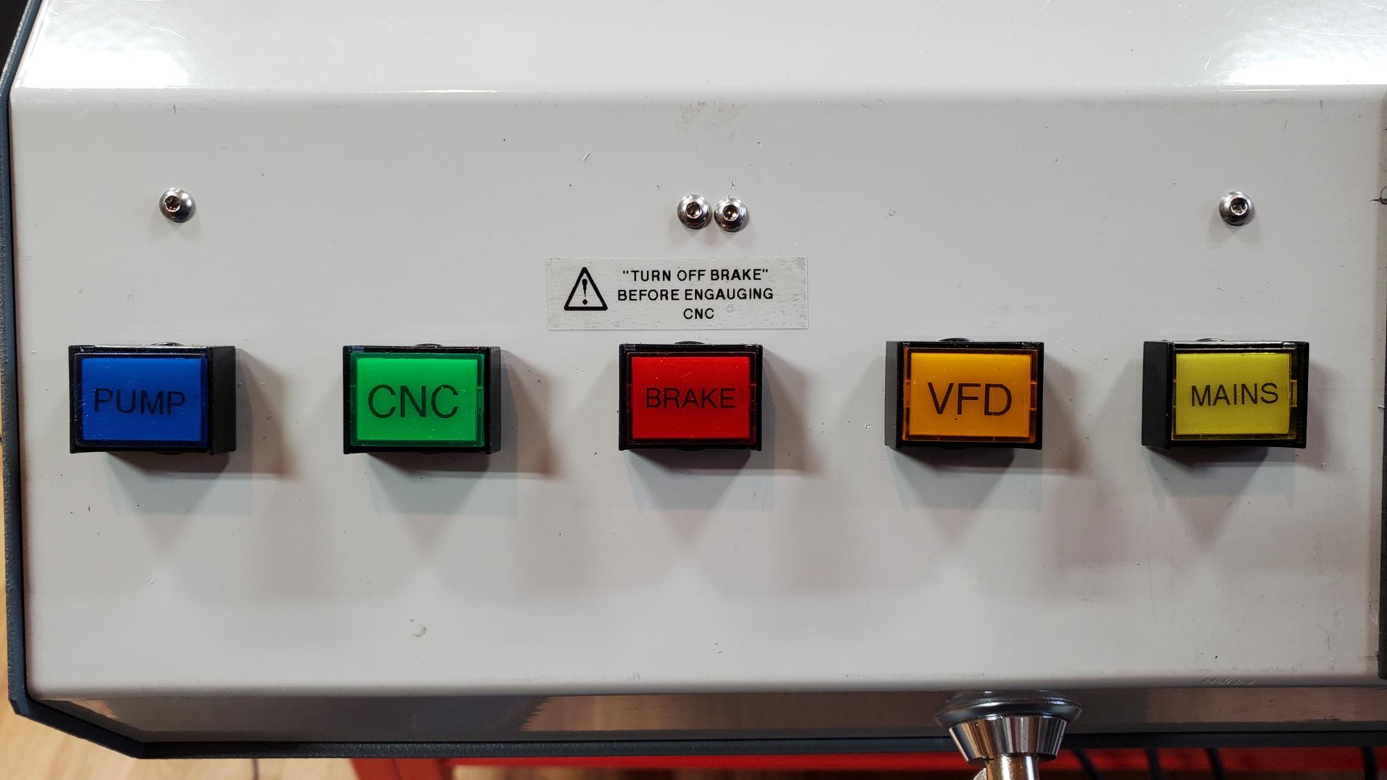
The VFD control panel has been relocated from the VFD unit with the use of an extension kit. The push buttons have LED illumination to indicated their status.
The switches in-turn control SSR (Solid State Relays) located in an electrical enclosure, that is well grounded and provides EMF shielding.
The SSR's also eliminate noise associated with mechanical relays. It should be noted, that HY does not recommend contactors i.e. mechanical relays due to EMF noise.
Shapeoko 5 Pro 4 X 4 Modifications.
As a longtime user of the original Shapeoko 3, I have recently upgraded the shop to the Shapeoko 5 Pro with a 4 x 4 table.
With this upgrade I added a control panel for the machine, as the VFD and CNC controllers were out of easy reach. I designed the control panel to use low voltage TTL (Transistor-to-Transistor Logic), so that no mains' voltage would be present at the controls.
The VFD is a HY 2. 2KW 220 Volt water cooled 80mm spindle and is controlled by the CNC Carbide Motion Ver. 636 software. This allows for automatic spindle speeds and feeds.
The control panel is mounted to an under desk keyboard mount. The control panel controls the spindle water pump, the VFD, CNC controller, master power, Emergency Stop and an optional Z-Axis brake. Additionally the front has a keyed lockout.

The SSR's and wiring blocks are mounted to DIN rails for easy servicing and modifications. This was much needed during the design stage. Note the below photo is during prototype design, so the wiring is a mess. The wiring is run in liquid tight flexible conduit to keep dust and moisture out.
12 Volt DC supply for logic control.

The Brake Revisited
After using the brake to compensate for the weight of the 80mm spindle on the Z-Axis, it was found to be too effective. It would be necessary to fast switch the power to the CNC controler off and the Brake on at the same time. This is due to the Z-Axis motor still having residual power with the Brake ON and the possibility of damaging the Z-Axis Motor. It was also found that the Brake gets hot when left on. This heat can transfer into the the Z-Axis Motor. A possible redesign of braking system would be to add a heat sink and a delay timer to the brake. So for now I have a thick foam pad to place under the Z-Axis when the power to the CNC controller is turned off. This works fine as long as the bit is not hot. I have since reassigned the brake buton to the vacuum.

Trials and Tribulations.
After using the Shapeoko 3 for many years I have the upgrade to 5 Pro 4X4 a good investment. The only major flaw was the BitSetter not operating. Carbide support sent a new BitSetter end cap end cap PCB without hassle. I later found after replacing them that it was a known cable issue, with the cable that runs from the front end cap PCB and the plug at the rear of the machine. In the photo you can see the brown and black wires are swapped. This only affected the BitSetter but not the Green Led on the end cap.

Work Holding.
I am using cookies (round tree stock) and using 8020 brackets to hold the rounds. By placing a small of folded 80 grit sandpaper between the bracket and work, I get great holding power.


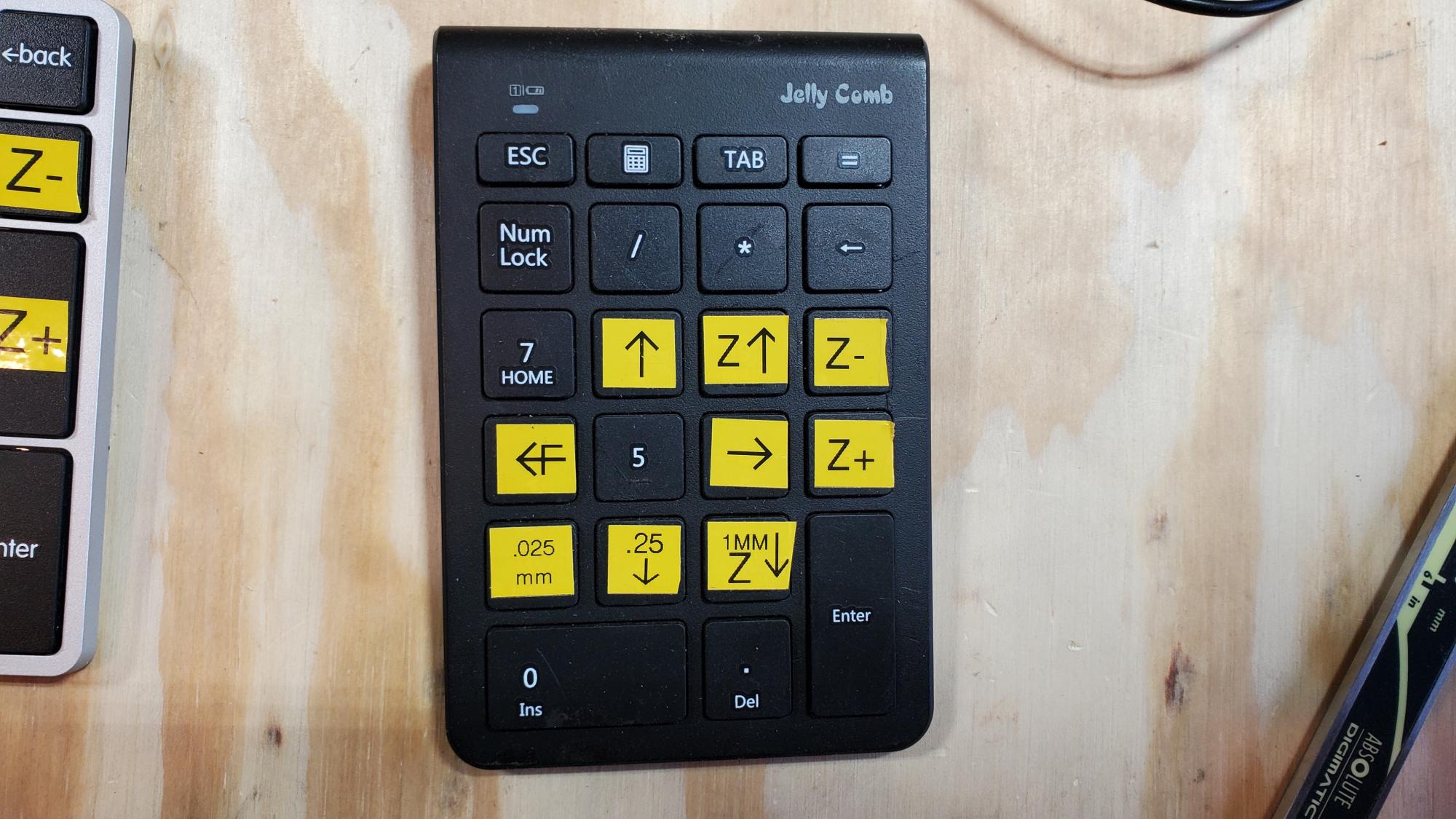
Jogging and alignment.
The use of a small keypad is a lifesaver for alignment on the large 4X4 table. Cordless units work fine when working at the far end of the table, but are a little less responsive than the corded units, especially when the battery is weak or the receiver is far away.

Initialzation Failures.
I was fought with initialzation failures resulting in G-Code errors. The errors were randon but were more prevalent during loading a new job. I went through the list of online fixes by checking the ball screws, homing sensors, sensor alignment and table alignment.
With errors still occurring, I removed both Y-Axis motors and checked the clutches and found them to be tight and aligned. While the motors were off the machine, I placed two 1-2-3 Blocks between the frame and Y-Axis's while manually moving both ends of the Y Axis to align with the blocks at the back travel of the maching. Then I carefully reinstalled the motors as to keep the Y axis parked on the blocks and parallel to the frame. As of this writing, this seams to have fixed the issue. This would lead me to believe the Y was slightley out of parallel.